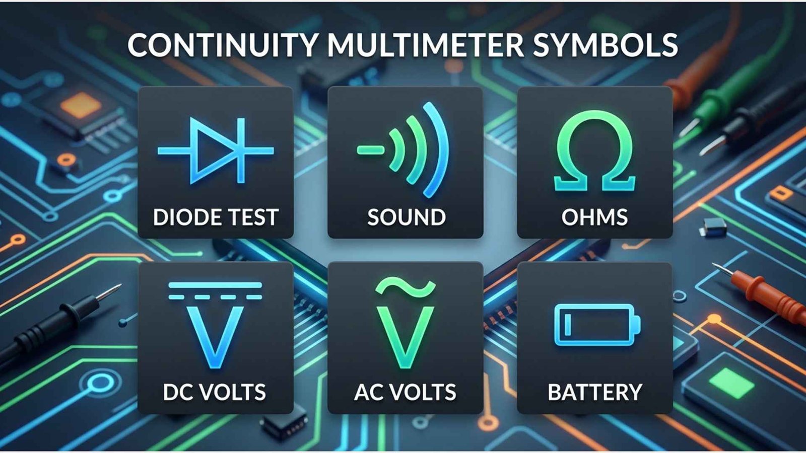
Continuity multimeter symbols identify the setting used to check whether electricity has an unbroken path through a wire, fuse, switch, connector, or other component.
The symbol usually looks like a speaker, sound waves, or curved lines radiating from a dot. On some meters, it shares a dial position with the resistance symbol Ω or the diode symbol.
This small icon matters because continuity testing is one of the fastest ways to locate broken wires, blown fuses, faulty switches, loose connections, and damaged circuit-board tracks. You may see it on digital multimeters, clamp meters, automotive testers, electrical diagrams, product manuals, and LCD displays.
Quick Meaning
The continuity multimeter symbol represents audible continuity testing. When this mode is selected, the meter sends a small test current through a de-energized circuit. If resistance is below the meter’s specified threshold, it usually beeps and displays a low resistance value. No beep or an “OL” reading generally indicates an open path.
Continuity Multimeter Symbol Overview
| Field | Details |
| Symbol name | Continuity symbol, audible continuity symbol, or continuity beeper symbol |
| Common appearance | Speaker icon, sound-wave icon, radiating curved lines, or buzzer mark |
| Primary meaning | Tests whether an electrical path is complete |
| Technical category | Electrical measurement and diagnostic symbol |
| Main measurement | Very low electrical resistance |
| Typical dial location | Alone or shared with Ω, diode, or capacitance mode |
| Common result | Beep and low resistance for continuity |
| Open-circuit result | “OL,” “1,” infinity, or no audible tone |
| Common uses | Testing wires, fuses, switches, connectors, relays, and circuit traces |
| Test condition | Circuit must normally be powered off |
| Related symbols | Ω, diode symbol, COM, VΩ, ground, AC, and DC |
| Unicode character | No single standardized Unicode character represents every meter’s continuity icon |
| Emoji equivalent | No official equivalent; 🔊 is sometimes used informally |
| Symbol standardization | General meaning is consistent, but appearance and thresholds vary by manufacturer |
What Do Continuity Multimeter Symbols Mean?
Continuity multimeter symbols mean that the meter is ready to check for a complete, low-resistance electrical connection between its two probes.
In electrical work, continuity means that current can travel through a path without being stopped by a break. A wire with an intact conductor normally has continuity from one end to the other. A blown fuse, broken wire, open switch, or disconnected terminal normally does not.
When continuity mode is active, the multimeter applies a small internal voltage through the test leads. It then measures the resistance between the probe tips. If that resistance falls below a preset value, the meter activates its buzzer.
The beep is a practical convenience. It lets a technician concentrate on the probes instead of constantly looking at the display. This is especially useful when tracing cables, checking several terminals, or working in a confined location.
However, the continuity symbol does not mean that a component has zero resistance. It means the resistance is low enough to meet that meter’s continuity threshold.
What Does the Continuity Symbol Look Like?
The most common continuity symbol resembles sound waves leaving a small point or speaker. It may appear as:
- A small speaker with curved sound-wave lines
- A dot or vertical line followed by several curved lines
- Three or four expanding arcs
- A buzzer-like icon
- The word CONT
- A sound-wave mark beside Ω
- A sound-wave mark beside the diode symbol
The exact design varies because multimeter manufacturers use different dial layouts and display graphics. Klein Tools manuals, for example, identify the radiating sound-wave mark as the symbol for audible continuity. Keysight also describes continuity mode as commonly represented by a sound-wave icon.
On compact multimeters, several functions may share one dial position. You may need to press a button marked SELECT, SEL, FUNC, or MODE until the continuity icon appears on the LCD.
History and Origin of the Continuity Symbol
The continuity symbol developed from the audible test function used in electrical measuring instruments. It is not an ancient cultural symbol and does not have a religious, mythological, or ceremonial origin.
Early electrical technicians checked continuity with simple devices such as batteries, lamps, bells, galvanometers, and dedicated circuit testers. If the test circuit was complete, the lamp illuminated, the bell sounded, or the meter needle moved.
As analog multimeters became common, users often tested continuity through the resistance ranges. A low resistance reading and strong needle movement indicated a complete connection. These instruments did not always include an electronic buzzer.
Digital multimeters made audible continuity testing more practical. Manufacturers added circuitry that compared measured resistance with a predetermined threshold. When the measured value fell below that level, an electronic beeper sounded.
The modern continuity icon therefore evolved from a functional idea: sound confirms connection. Its curved lines visually represent sound waves, much like speaker and volume symbols used on radios, computers, phones, and other electronic devices.
Unlike the ohm symbol, which comes from the Greek letter omega, the continuity icon has no single ancient alphabetic source. It is primarily a pictogram designed for quick recognition.
Symbolism and Interpretation
The continuity symbol has a direct technical meaning rather than a broad cultural one. Still, its visual design communicates several useful ideas.
Connection
Its main concept is connection. A beep indicates that two tested points are joined through a sufficiently low-resistance path.
Uninterrupted Flow
The symbol represents an uninterrupted route through a conductor or closed component. It helps distinguish a complete path from an electrical break.
Confirmation
Because the meter produces a sound, the icon also represents immediate confirmation. The user does not have to interpret a complex value before knowing that a connection exists.
Positive Interpretation
In troubleshooting, a continuity beep can be positive when confirming:
- An intact fuse
- A closed switch
- A correctly connected wire
- A bonded ground conductor
- A complete circuit-board trace
- A secure cable connection
Negative Interpretation
A beep can also reveal a problem. For example, unexpected continuity between two conductors may indicate:
- A short circuit
- Damaged insulation
- Solder bridging
- Incorrect wiring
- Unwanted contact with ground
- Internally shorted components
The meaning therefore depends on what the circuit is supposed to do. Continuity is not automatically “good,” and an open circuit is not automatically “bad.”
Psychological Interpretation
The symbol’s sound-wave design reduces mental effort. A technician can treat the beep as rapid sensory feedback while keeping both eyes on the probes and test points.
However, relying only on sound can create false confidence. Accurate diagnosis still requires an understanding of resistance values, circuit design, parallel paths, and the meter’s operating specifications.
Scientific and Technical Meaning
Continuity testing is fundamentally a low-resistance measurement.
Relationship Between Continuity and Resistance
Electrical resistance describes how strongly a material opposes current. It is measured in ohms and represented by Ω.
A good conductor normally has low resistance. An open circuit has extremely high resistance because no complete conductive path exists.
In simplified form:
- Low resistance: likely continuity
- Very high resistance: likely open circuit
- Unexpected moderate resistance: may require further investigation
The continuity function does not usually demand exactly 0 Ω. Real test leads, wire, contacts, terminals, and connections all contribute some resistance.
How the Meter Performs the Test
A digital multimeter typically:
- Uses its internal battery to produce a small test voltage.
- Applies that voltage through the test leads.
- Measures the resulting current or resistance.
- Compares the measurement with a programmed threshold.
- Sounds the buzzer when the threshold condition is met.
Open-circuit test voltage and short-circuit current vary among models. That variation can matter when testing sensitive electronic circuits.
Continuity Thresholds Vary
There is no universal resistance value at which every meter beeps.
One Klein Tools meter specifies an audible signal below 100 Ω, while another specifies continuity below 50 Ω. A different model uses a threshold below 25 Ω.
This means two multimeters can test the same object and behave differently. A long cable, resistive coil, lamp filament, or corroded connection might make one meter beep while another remains silent.
Always check the user manual when the exact threshold matters.
What “OL” Means
In continuity mode, OL usually means open loop, overload, over limit, or a resistance too high for the selected range. It normally indicates that the meter cannot detect a sufficiently conductive path between the probes.
Some older or manual-ranging meters may display:
- The number 1 at the far left
- An infinity-like indication
- A blank or unchanged display
- A very high resistance value
The display convention depends on the meter.
Why Probe Resistance Matters
Touching the two probe tips together rarely produces a perfect 0.000 Ω reading. The leads, probe contacts, input jacks, and internal circuitry add resistance.
A small reading such as 0.1 Ω, 0.3 Ω, or 0.8 Ω may be normal, depending on the meter and leads. Dirty or damaged probe tips can increase the reading.
Some advanced meters include a relative or zero function that subtracts lead resistance from later measurements.
How to Use the Continuity Symbol on a Multimeter
Continuity mode should normally be used only on a circuit that is disconnected from power.
Step 1: Turn Off the Power
Disconnect the equipment from the electrical supply. Remove batteries where practical, unplug power cords, and switch off the relevant breaker.
Do not assume that a switch has removed all dangerous voltage. Verify the circuit is de-energized using an appropriate voltage-testing procedure.
Step 2: Discharge Capacitors
Capacitors can store electrical energy after power has been removed. Discharge high-voltage capacitors according to the equipment manufacturer’s service procedure.
Step 3: Connect the Test Leads
Insert:
- The black lead into the COM jack
- The red lead into the VΩ or VΩmA jack specified by the meter
Do not place the red lead in the high-current input unless the meter’s instructions specifically require it. Continuity tests normally use the voltage-and-resistance input.
Step 4: Select the Continuity Symbol
Rotate the dial to the sound-wave or speaker symbol.
When continuity shares a setting with resistance, diode testing, or capacitance, press SELECT, SEL, or MODE until the continuity icon appears on the display.
Step 5: Test the Meter First
Touch the two probe tips together.
A working meter should generally:
- Produce a beep
- Display a low resistance
- Show a continuity icon or indicator
This quick check confirms that the test leads, jacks, battery, and buzzer are functioning.
Step 6: Test the Component
Place one probe at each end of the conductor, fuse, switch, or circuit path.
Interpret the result according to the expected circuit state:
| Meter result | Likely interpretation |
| Steady beep and very low resistance | Complete low-resistance path |
| No beep and OL | Open circuit or resistance above threshold |
| Intermittent beep | Loose, broken, dirty, or unstable connection |
| Beep with unexpectedly high displayed value | Meter has a high continuity threshold |
| Beep where isolation is expected | Possible short or parallel circuit path |
Step 7: Confirm Important Results
For critical work, do not rely on the beep alone. Read the displayed resistance and compare it with:
- The manufacturer’s specification
- The expected resistance of the component
- A known-good component
- The wiring diagram
- The meter’s continuity threshold
Where Continuity Multimeter Symbols Are Used
Digital Multimeters
Most modern digital multimeters include continuity mode. The symbol may appear on the rotary selector, display, or both.
Clamp Meters
Many clamp meters combine current measurement with voltage, resistance, diode, and continuity functions.
Automotive Electrical Testing
Mechanics use continuity mode to inspect:
- Wiring harnesses
- Fuses
- Ground connections
- Switches
- Relays
- Connectors
- Lighting circuits
The vehicle circuit must be isolated correctly because electronic control modules and parallel paths can affect results.
Household Electrical Work
Continuity testing can help inspect de-energized:
- Extension cords
- Appliance cables
- Switches
- Heating elements
- Fuses
- Protective conductors
- Lamp holders
Household electrical systems can be dangerous. Continuity mode is not a substitute for correct lockout, voltage verification, protective equipment, or professional training.
Electronics Repair
Technicians use the mode to trace printed circuit board tracks, inspect solder joints, locate shorted power rails, and verify connector pins.
Cable Identification
A technician can determine which conductor appears at the far end of a multi-core cable by checking each wire for continuity.
Manufacturing and Quality Control
Continuity testing confirms that assembled wires, terminals, connectors, switches, and circuit-board traces meet basic connection requirements.
Common Variations of the Continuity Symbol

Sound-Wave Symbol
This is the most recognizable design. It shows curved lines expanding outward to represent an audible tone.
Speaker Symbol
Some devices use a miniature speaker icon similar to a computer volume symbol.
Continuity and Resistance Combined
The sound-wave icon may appear beside Ω because continuity testing is based on resistance measurement.
Continuity and Diode Combined
Compact meters often place continuity and diode testing at the same selector position. A function button switches between them.
“CONT” Label
Some instruments use the abbreviation CONT instead of, or in addition to, a pictogram.
LCD-Only Symbol
A meter may show several functions around one dial position and reveal the active function only on its screen.
Light and Sound Indicators
Certain meters combine the buzzer with an LED. The light can help in noisy workplaces where the tone is difficult to hear.
Continuity Symbol vs. Similar Multimeter Symbols
Continuity Symbol vs. Ohms Symbol
The continuity symbol checks whether resistance is low enough to indicate a connected path. The Ω mode measures resistance more precisely across the meter’s available ranges.
Use continuity for rapid pass-or-fail checks. Use resistance mode when the actual value matters.
Continuity Symbol vs. Diode Symbol
The diode symbol resembles a triangle-free arrowhead or filled triangle-like wedge pointing toward a vertical bar, depending on the printed style. Diode mode measures forward voltage drop and checks one-way semiconductor behavior.
Continuity mode looks for a low-resistance path without primarily evaluating diode junction voltage.
Continuity Symbol vs. Buzzer or Volume Symbol
The icons may look similar because both represent sound. On a multimeter, the sound-wave icon is tied to electrical continuity rather than media volume.
Continuity Symbol vs. Ground Symbol
The ground symbol usually consists of descending horizontal lines or a vertical line ending in a ground mark. It represents an electrical reference, protective earth, or chassis connection.
It does not indicate continuity mode, although continuity testing may be used to inspect grounding conductors.
Continuity Symbol vs. AC and DC Symbols
A wavy line represents alternating current or voltage. A solid line over a dashed line represents direct current or voltage.
Neither is a continuity symbol, even though the wavy AC mark may superficially resemble part of a sound-wave design.
Common Misconceptions
A Beep Always Means the Circuit Is Good
A beep proves only that the meter detected a path below its threshold. It does not prove that the connection can safely carry the required current.
A corroded joint might pass a low-current continuity test but fail under normal load.
No Beep Always Means a Broken Wire
The resistance may simply exceed the buzzer threshold. Coils, bulbs, long cables, resistors, and electronic components can show measurable resistance without triggering the tone.
Continuity Mode Can Be Used on Live Circuits
Continuity and resistance modes should generally not be applied to energized circuits. External voltage can produce false readings, damage the meter, blow an internal fuse, or expose the user to shock and arc hazards. Manufacturer instructions repeatedly warn users to remove circuit power before continuity testing.
A 0 Ω Reading Is Required
Real conductors and test leads have resistance. A reading slightly above zero can still indicate excellent continuity.
All Multimeters Use the Same Beep Threshold
Thresholds vary widely. The manual is the only reliable source for a specific model’s exact behavior.
The Continuity Symbol Is the Diode Symbol
They are separate functions, even when they share a dial setting. Select the correct mode on the screen before testing.
Polarity Matters for Every Continuity Test
For a simple wire, fuse, or mechanical switch, probe polarity normally does not matter. It can matter when semiconductors, polarized parts, or complex electronic circuits remain connected.
A Beep Identifies the Intended Path
Parallel components can create an alternate route. In-circuit testing may therefore produce a beep even when the specific wire or component being examined is open.
Interesting Facts About Continuity Multimeter Symbols
- The symbol represents sound, not electricity itself.
Its curved lines show the audible feedback produced by the meter rather than the shape of a circuit. - Continuity is measured through resistance.
Although it appears as a separate function, the test relies on a simplified low-resistance measurement. - The beep threshold is manufacturer-dependent.
Different models may beep below 25 Ω, 50 Ω, 100 Ω, or another specified value. - A fast buzzer is important for professional work.
Slow continuity response can make rapid wire tracing frustrating because the user must hold each probe in place longer. - Some meters latch the beep.
The sound may continue briefly after contact changes, making a momentary connection easier to notice. - Silence can be intentional.
Certain meters allow the buzzer to be disabled while still displaying continuity or resistance results. - A continuity beep does not test insulation quality.
Proper insulation resistance testing often requires specialized equipment and a much higher test voltage. - Circuit boards can create misleading continuity.
Capacitors may charge, semiconductors may conduct in one direction, and parallel components may form temporary or alternate paths. - Intermittent beeping can locate hidden cable damage.
Gently moving a cable during testing may reveal a broken conductor that connects only at certain angles. - The continuity icon has no universal Unicode equivalent.
Manufacturers typically create it as a custom graphic rather than using a standard text character. - The function can test both desired connections and unwanted shorts.
Technicians use the same symbol to confirm proper wiring and to detect conductors that should remain isolated. - Audible testing improves visual safety and control.
Users can watch probe placement instead of repeatedly turning toward the display, although safe procedures remain essential.
Related Multimeter Symbols
Ohms: Ω
The omega symbol represents resistance. It provides numerical resistance measurements rather than a simple audible connection check.
Diode Symbol
The diode-test icon represents semiconductor junction testing. It typically displays forward voltage drop instead of ordinary resistance.
Direct Voltage: V⎓
A V with a solid and dashed line represents DC voltage, commonly used for batteries, vehicle systems, and electronic power supplies.
Alternating Voltage: V~
A V with a wavy line represents AC voltage, commonly used for building wiring and mains-powered equipment.
Common Terminal: COM
COM identifies the jack that normally receives the black test lead.
Voltage and Resistance Input: VΩ
This jack normally receives the red lead for continuity, resistance, voltage, and often diode testing.
Ground Symbol
The ground icon identifies protective earth, chassis, or a circuit reference point. It is not a testing mode.
Capacitance Symbol
The capacitance icon often resembles two parallel plates. It is used for measuring capacitor values and may share a selector position with continuity or diode mode.
Frequently Asked Questions
What is the continuity symbol on a multimeter?
The continuity symbol usually looks like a speaker or several curved sound waves. It activates a low-resistance test that produces a beep when the meter detects a sufficiently complete conductive path. Some models combine this symbol with Ω, diode, or capacitance functions, requiring a SELECT or MODE button.
What setting should I use to test continuity?
Turn the selector to the sound-wave, speaker, or CONT symbol. Insert the black lead into COM and the red lead into the VΩ input. If several functions share the dial position, press the function-selection button until the continuity icon appears on the display.
What does a beep mean during a continuity test?
A beep means the measured resistance is below the meter’s programmed continuity threshold. It usually indicates a connected path, but it does not prove that the connection is perfect or capable of carrying full operating current. Check the displayed resistance when connection quality matters.
What does OL mean in continuity mode?
OL normally indicates an open circuit, an out-of-range condition, or resistance too high for the meter to recognize as continuity. It may result from a broken wire, open switch, blown fuse, poor probe contact, or component resistance above the selected range.
Can I test continuity on a live circuit?
No. Continuity testing should normally be performed only after power has been removed and stored energy has been safely discharged. Applying continuity mode to an energized circuit can create false results, damage the meter, or expose the user to electrical shock and arc hazards.
Why does my multimeter not beep even though it shows resistance?
The displayed resistance may be higher than the meter’s audible threshold. For example, a meter could display 120 Ω but beep only below 50 Ω. The component may still conduct electricity, but it does not meet that model’s programmed definition of audible continuity.
Why does my multimeter beep when the probes are not touching?
The probes may be contacting through the circuit, moisture, contamination, conductive debris, a parallel component, or damaged insulation. Inspect the leads, separate the component from the circuit when possible, and compare the resistance reading with the service information.
Is continuity the same as zero resistance?
No. Continuity means the resistance is low enough to form a conductive path according to the meter’s threshold. Test leads, contacts, conductors, and terminals naturally add small amounts of resistance, so a good connection does not have to display exactly 0 Ω.
Can continuity mode test a fuse?
Yes. After removing power, place one probe on each fuse terminal. A good low-resistance fuse usually produces a beep and a reading near zero ohms. A blown fuse usually produces no beep and displays OL. Remove the fuse from the circuit when parallel paths could affect the result.
Can I use continuity mode to find a short circuit?
Yes. With power removed, continuity testing can identify an unwanted low-resistance path between conductors, terminals, or a power rail and ground. However, some circuits naturally show low resistance, so compare the result with a schematic, specifications, or a known-good unit before declaring a short.
Key Takeaways
- The continuity multimeter symbol usually resembles a speaker or sound waves.
- It identifies the audible low-resistance testing mode.
- A beep indicates resistance below the meter’s continuity threshold.
- The exact beep threshold varies among manufacturers and models.
- OL usually means an open path or resistance above the measurable range.
- Continuity tests should normally be performed only on de-energized circuits.
- A beep does not automatically prove that a connection is safe or healthy.
- Resistance values provide more detail than sound alone.
- Continuity mode can locate broken wires, blown fuses, faulty switches, and unwanted shorts.
- Always consult the multimeter’s manual for model-specific symbols and limits.
Conclusion
Continuity multimeter symbols make one of the most useful electrical tests easy to recognize. The speaker or sound-wave icon tells you that the meter can check for a complete, low-resistance path and provide an audible response when its threshold is met.
Understanding the symbol is only the beginning. Reliable testing also requires correct lead placement, an unpowered circuit, awareness of parallel paths, and careful interpretation of the displayed resistance. Once these principles are understood, continuity mode becomes a fast and practical tool for diagnosing wires, fuses, switches, connectors, and electronic circuits.

I am Ethan Mitchell, an English writer and lifelong learner who is fascinated by words and the way language changes over time. At LearnNestly, I share practical explanations designed for readers who want to improve their understanding of English without complicated terminology. I enjoy researching meanings, usage, grammar, and common language mistakes, then presenting the information in a simple and useful format. My purpose is to make every article a small learning experience that readers can actually apply.
Books:
- The Smart Learner’s English Guide
- English in Real Life
 Daniel Brooks
 Amelia Carter