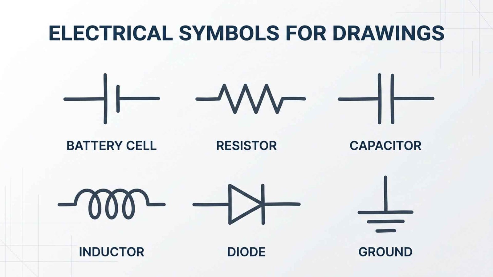
Electrical symbols for drawings are standardized graphic marks that represent wiring, devices, equipment, connections, and electrical functions. Instead of drawing every outlet, switch, motor, or circuit breaker in realistic detail, designers use compact symbols that trained readers can recognize quickly.
You may encounter these symbols on residential floor plans, commercial construction documents, circuit schematics, industrial control diagrams, single-line diagrams, panel schedules, wiring diagrams, and equipment manuals.
Learning what they mean helps electricians, engineers, architects, technicians, students, inspectors, and property owners understand how an electrical system should be installed or operated.
Quick Meaning
Electrical symbols for drawings are visual shorthand used to identify electrical components and show how they connect or function. A symbol may represent a receptacle, light fixture, switch, transformer, motor, ground connection, circuit breaker, battery, resistor, or another device. Its exact meaning depends on the drawing type, applicable standard, and project legend.
Electrical Symbol Overview Table
| Field | Description |
| Symbol system | Electrical and electronic graphical symbols |
| Primary purpose | Represent components, functions, wiring, and connections |
| Main categories | Architectural, power, lighting, control, electronic, communication, and safety |
| Common drawing types | Floor plans, schematics, wiring diagrams, one-line diagrams, riser diagrams, and P&IDs |
| Major international reference | IEC 60617 |
| Common North American reference | NECA 100 and project-specific drafting standards |
| General diagram standard | ISO 14617 |
| Common users | Electricians, engineers, architects, technicians, contractors, and inspectors |
| Common format | Lines, circles, letters, geometric shapes, and standardized marks |
| Unicode | Usually not applicable |
| Emoji equivalent | None |
| Interpretation method | Read the symbol together with the legend, labels, notes, and line types |
| Key limitation | Symbols may vary between countries, industries, standards, and companies |
The IEC identifies IEC 60617 as its official source for electrotechnical diagram symbols, containing roughly 1,900 symbols. North American construction drawings may follow NECA 100, while industrial and process drawings may also use standards such as ISO 14617 or ANSI/ISA 5.1.
What Do Electrical Symbols for Drawings Mean?
Electrical symbols represent either a physical component, an electrical function, a connection, or a location where equipment must be installed.
For example, a circle with identifying marks may represent a ceiling light, while a small circle containing letters may identify a switch type. A zigzag or rectangular shape may represent a resistor on a schematic. Parallel lines of unequal length often identify a cell or battery. A ground symbol shows that a conductor or equipment enclosure connects to a grounding point.
The symbol alone does not always provide the full meaning. Electrical drawings normally combine symbols with:
- Device tags
- Circuit numbers
- Wire sizes
- Voltage ratings
- Panel names
- Equipment schedules
- Installation notes
- Line types
- Abbreviations
- Cross-references
A receptacle symbol labeled “GFCI,” for instance, does more than indicate an outlet. The label specifies that the receptacle or its circuit requires ground-fault protection. Likewise, a light fixture marked “A” may refer to fixture type A in a separate lighting schedule.
This is why professional drawings should always include a legend or symbol list. Even when symbols are widely recognized, the legend confirms how the designer uses them on that specific project.
History and Origin of Electrical Drawing Symbols
Electrical symbols developed because early engineers needed a practical way to document increasingly complex systems.
During the nineteenth century, electrical diagrams became more important as telegraph networks, power systems, electric lighting, motors, and communication technologies expanded. Detailed pictures of every device were too slow to create and difficult to reproduce. Engineers gradually replaced realistic illustrations with simplified lines and geometric marks.
Early symbol systems were not fully uniform. A component might appear differently in drawings produced by different companies, industries, or countries. As electrical equipment became more interconnected, inconsistent notation created communication problems.
Professional societies and standards organizations began developing common symbol conventions. These systems allowed engineers and tradespeople to read diagrams without depending entirely on the original designer’s personal drawing style.
Today, IEC 60617 serves as a major international reference for graphical symbols used in electrotechnical diagrams. The IEC also advises technical authors to use symbols from IEC 60617 when preparing electrotechnical figures.
ISO 14617 provides broader rules for graphical symbols used in diagrams. Its current general-rules edition, ISO 14617-1:2025, covers the preparation and presentation of symbols related to industrial components, products, and processes.
In North America, construction drawings commonly use symbol conventions associated with architectural and electrical construction practice. NECA 100-2024 describes symbols for electrical wiring, equipment, electronic systems, and communications systems on construction documents.
The result is not one universal alphabet used identically everywhere. Instead, modern electrical drafting relies on several related systems shaped by region, industry, drawing purpose, and governing standards.
Symbolism and Interpretation
Electrical symbols are functional rather than symbolic in the cultural or spiritual sense. Their purpose is to communicate technical information with as little ambiguity as possible.
Shape communicates function
Basic shapes often establish the symbol’s category. Circles may indicate lamps, instruments, motors, or connection points. Rectangles may represent devices, equipment, resistors, panels, or control functions. Triangles may indicate direction, amplification, transformation, or warning, depending on context.
Lines communicate relationships
Lines are among the most important parts of any electrical drawing. They may represent:
- Conductors
- Cables
- Communication pathways
- Control signals
- Mechanical links
- Equipment boundaries
- Circuit continuations
A solid line may represent a physical wire on one drawing but a general circuit path on another. Dashed lines often indicate hidden wiring, optional equipment, control relationships, or nonphysical connections. The legend must define the intended meaning.
Orientation may affect meaning
Some symbols can be rotated without changing their meaning. Others show direction, position, or operating state. An arrow may indicate current flow, signal direction, movement, polarity, or adjustable operation.
Open and closed positions matter
Switches, relays, and contacts are normally shown in a defined reference state, often the de-energized or normal condition. A normally open contact appears separated. A normally closed contact appears connected.
“Normal” does not always mean the condition most frequently observed during operation. It generally means the state used by the chosen drafting convention, such as de-energized, unactuated, or at-rest.
Positive technical meaning
Electrical symbols support clarity, safety, coordination, maintenance, and repeatable construction. They allow a large amount of information to fit on a limited drawing area.
Negative interpretation
A symbol has no inherently negative meaning, but misreading it can create serious risks. Confusing neutral with ground, misidentifying a normally closed contact, or overlooking a circuit-breaker rating may lead to incorrect installation, equipment damage, or unsafe work.
Regional and Professional Significance
Electrical symbols vary because different regions and industries developed different drafting traditions.
International IEC practice
IEC-style symbols are widely used in international engineering, industrial machinery, electronics, power systems, and technical documentation. IEC 60617 is maintained as a database rather than only as a traditional printed symbol book.
United States and North America
American construction drawings may use symbols associated with NECA, architectural practice, engineering firms, utilities, and local authorities. Symbols on building plans can differ from those used in electronic schematics or machine-control diagrams.
For example, a receptacle on an architectural electrical plan may appear as a semicircular mark along a wall. That same device would be represented very differently on a circuit schematic showing its actual electrical connections.
Industrial process facilities
Refineries, chemical plants, manufacturing facilities, and water-treatment plants use specialized diagrams. Piping and instrumentation diagrams, commonly called P&IDs, combine process equipment, piping, instrumentation, and control relationships. ANSI/ISA 5.1 provides widely used identification and symbol conventions for instrumentation.
Company and utility standards
Large companies, public utilities, transit systems, factories, and government agencies may publish their own drafting manuals. These standards often build on national or international conventions but add custom abbreviations, line styles, equipment tags, and approval requirements.
The practical rule is simple: never assume that a familiar-looking symbol has exactly the same meaning on every drawing. Check the legend and applicable standard first.
Scientific and Technical Meaning
Electrical symbols organize technical information according to the type of drawing being created.
Architectural electrical plans
Architectural electrical plans show where devices are installed in a building. Common symbols include:
| Device | Typical meaning on a plan |
| Duplex receptacle | Standard two-outlet receptacle |
| GFCI receptacle | Ground-fault-protected receptacle |
| Single-pole switch | Controls one load from one location |
| Three-way switch | Controls one load from two locations |
| Four-way switch | Used between three-way switches for three or more control locations |
| Ceiling light | Ceiling-mounted lighting fixture |
| Recessed light | Fixture installed within the ceiling |
| Exit sign | Illuminated emergency-exit marker |
| Smoke detector | Device that detects smoke |
| Panelboard | Distribution panel containing protective devices |
| Junction box | Enclosure where conductors connect |
| Data outlet | Network or communication outlet |
These plans focus mainly on physical location and installation intent. They may not show the internal electrical operation of each device.
Schematic diagrams
A schematic shows how a circuit functions. It emphasizes electrical relationships rather than real-world placement.
Common schematic symbols include:
| Component | Function |
| Cell | Supplies direct-current voltage |
| Battery | Two or more cells or a battery source |
| Resistor | Limits current or creates a voltage drop |
| Variable resistor | Provides adjustable resistance |
| Capacitor | Stores electric charge |
| Inductor | Stores energy in a magnetic field |
| Diode | Primarily permits current in one direction |
| Light-emitting diode | Produces light when properly energized |
| Fuse | Opens when excessive current causes its element to melt |
| Circuit breaker | Opens a circuit under specified fault or overload conditions |
| Transformer | Transfers electrical energy through electromagnetic induction |
| Motor | Converts electrical energy into mechanical motion |
| Generator | Converts mechanical energy into electrical energy |
| Ground | Indicates a grounding or reference connection |
| Relay coil | Operates associated contacts |
| Normally open contact | Closes when actuated |
| Normally closed contact | Opens when actuated |
Wiring diagrams
A wiring diagram shows physical connection details. It may identify terminal numbers, conductor colors, connector pins, cable numbers, and wire routing.
Unlike a simplified schematic, a wiring diagram often helps technicians assemble, test, or repair actual equipment.
Single-line diagrams
A single-line diagram, also called a one-line diagram, represents a three-phase power system using one line rather than drawing every conductor separately.
It commonly shows:
- Utility service
- Transformers
- Switchgear
- Busbars
- Circuit breakers
- Disconnect switches
- Generators
- Panelboards
- Motors
- Grounding points
- Protective relays
- Metering equipment
One-line diagrams are essential for understanding power distribution, equipment ratings, protection, and system relationships.
Ladder diagrams
Ladder diagrams are widely used for motor control, relay logic, and industrial automation. Two vertical lines represent power rails, while horizontal “rungs” show control circuits.
A typical rung may contain a stop button, start button, overload contact, contactor coil, and holding contact. Reading from left to right helps the user understand the conditions required to energize the output.
Riser diagrams
A riser diagram shows how electrical or communication systems travel vertically through a building. It is useful for multistory power distribution, fire alarms, security, data systems, and telecommunications.
Where Electrical Symbols Are Used
Electrical symbols appear wherever technical teams must communicate electrical information.
Construction drawings
Architects and engineers use symbols to locate lighting, receptacles, switches, panels, alarms, emergency systems, and communication devices.
Equipment manuals
Manufacturers include wiring diagrams and schematics to support installation, operation, testing, and troubleshooting.
Industrial control systems
Factories use symbols for motors, sensors, programmable logic controllers, relays, solenoids, emergency stops, and safety circuits.
Utility systems
Electric utilities use one-line and three-line diagrams for substations, transmission, distribution, transformers, protective relays, and switching equipment.
Automotive and transportation systems
Vehicle wiring diagrams use symbols for batteries, lamps, switches, fuses, control modules, connectors, sensors, motors, and grounding points.
Electronics
Electronic schematics use symbols for resistors, capacitors, semiconductors, integrated circuits, antennas, connectors, oscillators, and signal sources.
Renewable-energy systems
Solar and energy-storage drawings may show photovoltaic modules, inverters, charge controllers, batteries, disconnects, meters, grounding equipment, and utility interconnections.
Fire alarm and security drawings
Specialized plans use symbols for smoke detectors, heat detectors, pull stations, notification appliances, door contacts, cameras, control panels, and communication pathways.
Common Electrical Symbol Variations
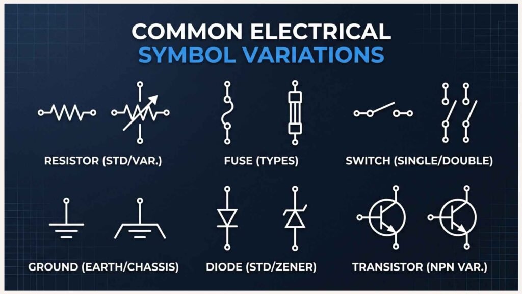
Electrical symbols change according to standard, region, and drawing purpose.
Resistor variations
A resistor is commonly shown as a zigzag line in traditional American diagrams. IEC-oriented diagrams often use a rectangle. Both can represent the same basic component.
Ground variations
Several ground symbols exist, including:
- Earth ground
- Protective earth
- Chassis ground
- Signal ground
- Functional ground
These terms are not automatically interchangeable. The symbol indicates the intended reference or protective function.
Switch variations
Switch symbols may identify single-pole, double-pole, three-way, four-way, momentary, keyed, selector, limit, pressure, float, or temperature-operated devices.
Transformer variations
Transformers may be shown with two coils, core lines, winding connections, polarity dots, taps, grounding arrangements, or phase configurations. A one-line symbol is usually simpler than a detailed schematic symbol.
Outlet variations
Architectural plans distinguish standard, split-wired, isolated-ground, weather-resistant, tamper-resistant, floor-mounted, ceiling-mounted, and special-purpose receptacles through added marks or labels.
Lighting variations
Lighting symbols may indicate fixture shape, mounting method, emergency function, switching group, lamp type, or schedule designation.
Regional adaptations
The same component may have a different outline under IEC, ANSI, JIS, British, or company standards. These differences do not necessarily indicate a different device.
Common Misconceptions
“Every symbol has one universal design”
Electrical symbols are standardized, but no single visual system governs every country, industry, and drawing type. Always check the project legend.
“A line always represents a physical wire”
A line may represent a conductor, cable, signal path, bus, mechanical relationship, or logical connection. Its meaning depends on the drawing.
“Crossing lines are always connected”
Crossing conductors may be connected only when a junction dot or other connection mark appears. Some older drafting conventions use a bridge or jump to show that one conductor crosses another without connecting.
“Ground and neutral mean the same thing”
Neutral is a current-carrying circuit conductor under normal operation. Equipment grounding conductors provide a fault-current path and support protection. They may be bonded at specific points, but they serve different functions.
“Normally open means usually open during everyday operation”
In control drawings, “normally” generally refers to the device’s defined reference state, often de-energized or unactuated. Operating conditions may keep the contact in the opposite state for long periods.
“Schematics show actual equipment locations”
Schematics show functional relationships. Floor plans, layouts, and wiring diagrams are better sources for physical placement.
“Color alone identifies a circuit”
Printed plans may appear in black and white, and conductor colors vary by system and region. Labels, tags, terminal numbers, and notes are more reliable than color alone.
“A familiar symbol can be interpreted without reading notes”
A symbol may be modified by letters, numbers, ratings, or schedule references. Ignoring those additions can change the meaning entirely.
Interesting Facts About Electrical Symbols
- IEC 60617 contains about 1,900 symbols.
This large number reflects the variety of electrical functions, devices, qualifying marks, and applications used across modern industries. - A symbol may describe function rather than appearance.
A relay symbol does not need to resemble the physical relay. It communicates what the device does within the circuit. - One device can appear differently on separate drawings.
A motor may use one symbol on a floor plan, another on a one-line diagram, and a more detailed representation on a control schematic. - Letter codes are often as important as shapes.
Tags such as M, CB, T, or LS can identify motors, circuit breakers, transformers, or limit switches, although exact conventions vary. - A dot can change an entire circuit.
At intersecting lines, a junction dot may indicate an electrical connection. Without it, the conductors may simply cross. - Contact symbols are linked across drawings.
A relay coil and its contacts may appear on different diagram locations. Cross-references help the reader find the associated parts. - One-line diagrams intentionally leave information out.
Their simplicity makes large power systems easier to understand, but detailed conductor and control information must be found elsewhere. - Symbols can be built from smaller symbol elements.
General shapes, qualifying marks, arrows, terminals, and identifiers combine to form more specific device symbols. - Architectural symbols are location-focused.
A receptacle symbol on a floor plan tells the installer where it belongs, not necessarily how its internal contacts are arranged. - Standards continue to evolve.
ISO published ISO 14617-1:2025 to provide current general rules for preparing and presenting graphical symbols for diagrams. - Digital drawing libraries can create inconsistency.
Computer-aided design software includes symbol blocks, but a block is not automatically correct merely because it came with the software. - The legend is part of the technical language.
A professional reader treats the legend, notes, schedules, and symbol list as essential parts of the drawing rather than optional reference material.
Related Electrical Symbols
Ground and protective-earth symbols
Both relate to grounding, but protective earth specifically supports protection against electric shock. Signal ground may instead provide an electrical reference for sensitive circuits.
Fuse and circuit-breaker symbols
Both represent overcurrent-protection devices. A fuse usually operates by melting an internal element and must be replaced. A circuit breaker can normally be reset after the cause of operation has been addressed.
Relay and contactor symbols
Both use an electrically operated coil to control contacts. Contactors are commonly designed for switching larger loads, such as motors and heating equipment.
Cell and battery symbols
A cell symbol represents one electrochemical source. A battery symbol may show multiple cells or identify a battery assembly.
Lamp and light-emitting diode symbols
Both produce light, but a general lamp symbol may represent a lighting load, while an LED symbol identifies a semiconductor diode that emits light.
Transformer and inductor symbols
Both use coils and magnetic fields. A transformer transfers energy between windings, while an inductor primarily stores energy in its own magnetic field.
Motor and generator symbols
A motor converts electrical energy into mechanical energy. A generator performs the reverse conversion.
Receptacle and junction-box symbols
A receptacle provides a connection point for plug-connected equipment. A junction box contains conductor splices, taps, or terminations and may not provide a user-accessible outlet.
Frequently Asked Questions
What are the most common electrical symbols on building drawings?
The most common symbols represent receptacles, switches, lighting fixtures, panelboards, junction boxes, smoke detectors, emergency lights, exit signs, communication outlets, and grounding points. Their exact shapes vary by drafting standard and design firm, so the project legend should always be checked before interpreting them.
Are electrical symbols the same in every country?
No. International projects often use IEC symbols, while North American construction documents may follow NECA, ANSI-related, or company standards. Some components have nearly identical symbols worldwide, but others, such as resistors, switches, receptacles, and grounding marks, can differ noticeably.
What is the difference between an electrical plan and a schematic?
An electrical plan shows the physical location of equipment within a building or site. A schematic explains how electrical components function and connect. Plans answer “Where is it installed?” Schematics answer “How does the circuit operate?” A complete project may require both.
How do I identify an unknown electrical symbol?
Start with the drawing legend. Next, read nearby labels, circuit numbers, notes, and schedule references. Identify the drawing type and applicable standard. If the meaning remains unclear, consult the designer, engineer, equipment manual, or governing symbol database rather than guessing.
What does a dot at the crossing of two lines mean?
A dot generally indicates that the conductors are electrically connected at a junction. Crossing lines without a dot may indicate that they do not connect, although drafting conventions differ. Because older and specialized drawings may use other methods, confirm the rule in the legend.
Why are some resistor symbols rectangular and others zigzag-shaped?
The two forms come from different drafting traditions. A zigzag resistor is common in American schematics, while a rectangular resistor is common in IEC-based drawings. Both represent resistance unless additional markings show a specialized resistor type.
What is the difference between ground, earth, and chassis symbols?
Earth or protective-earth symbols identify connections associated with the earth or electrical safety. Chassis ground connects to an equipment frame or enclosure. Signal ground provides a circuit reference. Their functions may overlap in some systems, but they should not be assumed to be identical.
Do electrical drawings show wire colors?
Some wiring diagrams specify wire colors through abbreviations, line colors, or conductor schedules. However, schematics and one-line diagrams may not show actual colors. Never rely on displayed color alone, especially when drawings may be copied, scanned, or printed in grayscale.
What standards govern electrical symbols?
IEC 60617 is a central international source for electrotechnical diagram symbols. ISO 14617 establishes broader diagram-symbol rules, while NECA 100 addresses North American electrical construction drawings. Specialized fields may also use standards such as ANSI/ISA 5.1 for instrumentation.
Can I use symbols included in CAD software without checking them?
Not safely. A CAD symbol library may contain outdated, regional, generic, or company-specific blocks. Before using a symbol, confirm that it matches the project’s governing standard, legend, drawing scale, and documentation requirements.
Key Takeaways
- Electrical symbols are visual shorthand for components, wiring, equipment, and electrical functions.
- Symbols differ between architectural plans, schematics, wiring diagrams, one-line diagrams, and control drawings.
- IEC 60617 is a major international source for electrotechnical diagram symbols.
- NECA 100 provides symbol guidance for North American electrical construction drawings.
- ISO 14617 establishes broader rules for graphical symbols used in technical diagrams.
- Shape alone may not provide the full meaning; labels, notes, schedules, and line types matter.
- Ground, neutral, protective earth, chassis ground, and signal ground are not automatically interchangeable.
- Crossing lines may or may not connect, depending on junction marks and drafting conventions.
- A project legend takes priority over assumptions based on familiar symbols.
- Electrical drawings should be interpreted by qualified people when installation or safety decisions are involved.
Conclusion
Electrical symbols for drawings create a shared visual language for designing, installing, operating, and maintaining electrical systems. They make complex plans easier to read by replacing realistic pictures with precise graphic marks for devices, circuits, connections, and functions.
However, accurate interpretation requires more than memorizing shapes. The reader must consider the drawing type, symbol legend, labels, notes, regional practices, and governing standards. By reading these elements together, you can understand electrical drawings more confidently and avoid the costly or dangerous mistakes that come from guessing.

I am Amelia Carter, an English language educator and educational writer who enjoys making difficult ideas simple and easy to understand. At LearnNestly, I write about English words, grammar, everyday expressions, and language questions that people often find confusing. I believe learning should feel practical, clear, and enjoyable rather than overwhelming. Through my writing, I try to give readers explanations they can understand and use in real life.
Books:
- The Everyday English Handbook
- Words Made Simple
 Daniel Brooks