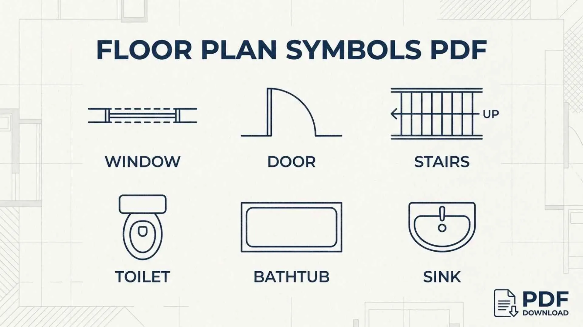
Floor plan symbols turn a complex building drawing into a visual language that architects, engineers, contractors, interior designers, and homeowners can understand. They represent walls, doors, windows, stairs, fixtures, appliances, electrical devices, structural elements, and other features without requiring long written descriptions.
A reliable floor plan symbols PDF works as a portable reference sheet that helps you identify these marks while reviewing house plans, renovation drawings, construction documents, real estate layouts, or interior design proposals.
However, symbols can vary between countries, design firms, software platforms, and construction disciplines, so the legend on the actual drawing should always be your primary guide.
Quick Meaning
Floor plan symbols are simplified graphic marks used to represent physical building elements and technical information from a top-down view. They show where walls, doors, windows, plumbing fixtures, electrical outlets, stairs, furniture, and equipment belong. A floor plan symbols PDF collects these conventions into an easy-to-read reference chart.
Floor Plan Symbols Overview Table
| Field | Description |
| Symbol category | Architectural and technical drawing symbols |
| Primary purpose | Represent building components clearly and efficiently |
| Common users | Architects, engineers, builders, designers, inspectors, and homeowners |
| Common formats | Printed plans, CAD drawings, BIM models, images, and PDF documents |
| Main disciplines | Architectural, structural, electrical, plumbing, mechanical, and fire protection |
| Typical symbols | Walls, doors, windows, stairs, fixtures, outlets, switches, and section markers |
| Origin | Developed through architectural and engineering drawing practices |
| Standardization | Partly standardized, but conventions vary by country, discipline, and organization |
| Modern use | Construction documents, permit drawings, real estate plans, and digital design |
| Unicode | Not generally applicable |
| Emoji equivalent | None |
| Related references | Legends, schedules, abbreviations, notes, details, and specifications |
What Do Floor Plan Symbols Mean?
Floor plan symbols represent objects, materials, movement, connections, and instructions that would be difficult to show realistically at a reduced scale.
A floor plan usually presents a building as though it has been cut horizontally and viewed from above. Walls appear as lines, openings interrupt those lines, and symbols identify the elements placed within or around the spaces. The drawing may also include dimensions, room names, identification tags, elevation markers, grid lines, and references to other sheets.
The meaning of a symbol depends on four main factors:
- Its shape
- Its position on the plan
- The drawing discipline
- The project legend or schedule
For example, a simple circle might represent a ceiling light on an electrical plan, a column on a structural drawing, or a numbered detail reference on an architectural sheet. Context prevents misinterpretation.
The United States National CAD Standard provides organized conventions for construction documentation, including drawing terms, sheet organization, schedules, plotting practices, and downloadable symbol resources. Even so, not every project uses identical graphics, and some symbols remain scale-dependent or office-specific.
History and Origin of Floor Plan Symbols
Floor plan symbols developed from the practical need to communicate building ideas accurately before construction began.
Early builders used sketches, measured diagrams, templates, and geometric layouts to organize structures. Ancient Egyptian, Greek, Roman, Chinese, and Mesopotamian builders all relied on forms of planning, measurement, proportion, and geometry. However, their drawing systems did not use one universal collection of modern architectural symbols.
As architecture became a formal profession, technical drawings grew more systematic. The development of descriptive geometry, mechanical reproduction, blueprinting, and standardized paper sizes allowed designers to produce more consistent construction documents.
During the industrial era, increasingly complex buildings required separate architectural, structural, mechanical, plumbing, and electrical drawings. Each discipline developed symbols that could communicate detailed information without overcrowding a plan with text.
Computer-aided design later transformed hand-drawn plans into precise digital files. Building information modeling expanded this process by connecting graphic objects with data such as dimensions, materials, model numbers, costs, and performance characteristics.
Modern standards help coordinate these systems. ISO 4157, for example, addresses designation systems for buildings, building parts, rooms, spaces, and related identifiers. It supports consistent naming and identification rather than defining every graphic icon found on every floor plan.
Today, PDF has become one of the most common formats for sharing construction drawings because it preserves page layout, text, linework, and scale information more reliably than many ordinary image formats.
Symbolism and Visual Interpretation
Floor plan symbols are functional rather than spiritual. Their “symbolism” comes from visual resemblance, drafting convention, and the need to communicate efficiently.
Pictorial Symbols
Some marks resemble the objects they represent. A toilet symbol resembles a bowl and tank viewed from above. A bathtub appears as a long rectangle with a curved interior. A bed usually appears as a mattress-shaped rectangle with pillows.
These symbols are easier for nonprofessionals to recognize.
Abstract Symbols
Other marks are more abstract. Electrical outlets, switches, smoke detectors, thermostats, and communication points may appear as circles, letters, short lines, or combinations of shapes.
Their meaning depends heavily on the legend.
Movement Symbols
Certain symbols describe movement instead of a fixed object. A curved arc beside a hinged door shows the direction in which the door swings. An arrow on a stair indicates whether the stair rises or descends from the level being shown.
Reference Symbols
Section marks, detail bubbles, elevation symbols, and callouts direct readers to another drawing. They act like links inside a document set.
Line-Based Meaning
Line weight, style, and pattern also carry information:
- Thick lines commonly identify major walls or cut elements.
- Thin lines may show fixtures, finishes, cabinetry, or secondary details.
- Dashed lines often represent objects above, below, behind, or otherwise hidden from the viewing plane.
- Wavy or irregular lines may indicate breaks or shortened views.
- Hatch patterns may distinguish materials or areas of work.
These conventions are useful, but they are not completely universal. The drawing legend and general notes take priority.
Common Architectural Floor Plan Symbols
Walls
Walls are usually shown as two parallel lines. Their thickness may suggest the type of construction, although the exact material must be confirmed through wall tags, details, or schedules.
Common wall variations include:
- Exterior walls
- Interior partitions
- Existing walls
- New walls
- Walls to be demolished
- Fire-rated assemblies
- Half-height walls
- Glazed partitions
Demolition plans often use dashed lines or a distinctive hatch, but the convention varies by project.
Doors
A standard hinged door appears as a straight door leaf connected to the wall, with a quarter-circle arc showing its swing path.
Common door symbols include:
- Single hinged door
- Double door
- Sliding door
- Pocket door
- Folding door
- Revolving door
- Overhead garage door
- Bi-fold closet door
A nearby circle, oval, or hexagonal tag may connect the opening to a door schedule containing its size, material, fire rating, hardware, and other requirements.
Windows
Windows usually appear as narrow breaks within a wall, often with one or more thin lines between the wall edges.
Variations may represent:
- Fixed windows
- Casement windows
- Sliding windows
- Double-hung windows
- Awning windows
- Bay windows
- Storefront glazing
- Curtain walls
Window tags link the symbol to a window schedule. The schedule should be consulted before assuming the exact style or dimensions.
Stairs
Stairs appear as a series of parallel lines representing treads. An arrow commonly indicates the direction of travel upward, while “UP,” “DN,” or similar labels clarify the change in elevation.
A break line may be used because part of the stair extends beyond the horizontal cutting plane.
Columns
Columns may appear as circles, squares, rectangles, or structural profiles. Their location often corresponds to numbered and lettered grid lines.
A column’s exact size and reinforcement usually appear on structural drawings rather than the basic architectural floor plan.
Plumbing Fixture Symbols
Plumbing symbols identify fixtures and equipment connected to water, drainage, or gas systems.
Common examples include:
| Symbol or label | Typical meaning |
| WC | Water closet or toilet |
| LAV | Lavatory or bathroom sink |
| SH | Shower |
| TUB | Bathtub |
| KS | Kitchen sink |
| FD | Floor drain |
| WH | Water heater |
| HB | Hose bibb |
| CW | Cold-water line |
| HW | Hot-water line |
| SAN | Sanitary drainage |
| VTR | Vent through roof |
On architectural plans, fixtures may be shown mainly to establish room layout and accessibility. Plumbing plans add pipe routes, sizes, slopes, valves, connections, and equipment information.
A toilet symbol does not by itself confirm its model, flushing system, accessibility rating, or installation requirements. Those details belong in schedules and specifications.
Electrical Floor Plan Symbols
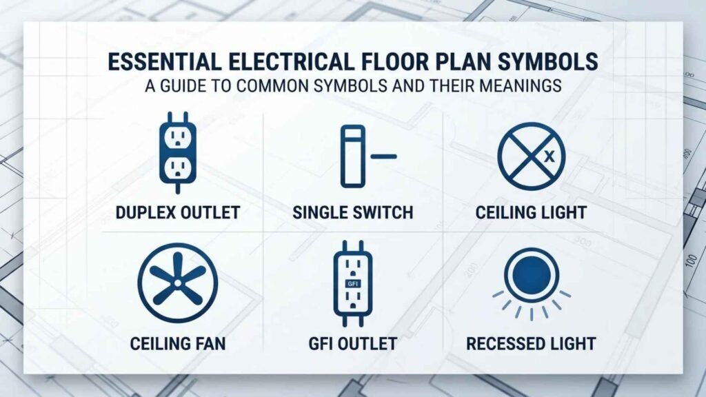
Electrical plans use symbols for lighting, power, communication, controls, and safety systems.
Common electrical symbols include:
- Duplex receptacle
- Ground-fault circuit-interrupter receptacle
- Floor outlet
- Single-pole switch
- Three-way switch
- Four-way switch
- Ceiling light
- Wall-mounted light
- Recessed downlight
- Pendant fixture
- Exhaust fan
- Smoke detector
- Carbon monoxide alarm
- Data outlet
- Telephone outlet
- Television outlet
- Electrical panel
Letters often modify the basic symbol. For example, a switch marked with a number or letter may indicate a specific switching arrangement or controlled fixture.
Curved or dashed control lines may connect switches with lights. These lines usually show functional relationships, not physical cable routes.
Because electrical symbol conventions differ, readers should never identify an unfamiliar circle or letter solely by appearance. The electrical legend provides the correct interpretation.
HVAC and Mechanical Symbols
Mechanical plans show heating, ventilation, air-conditioning, exhaust, and related equipment.
Common HVAC symbols include:
- Supply-air diffuser
- Return-air grille
- Exhaust-air grille
- Thermostat
- Ductwork
- Flexible duct
- Air-handling unit
- Fan-coil unit
- Furnace
- Condensing unit
- Damper
- VAV box
- Mechanical equipment tag
Arrows may indicate airflow direction. Duct dimensions commonly appear beside duct lines, while equipment tags connect components to mechanical schedules.
Rectangles with diagonal marks may represent diffusers or grilles, but their exact configurations vary. A reflected ceiling plan is often the best sheet for understanding ceiling-mounted HVAC devices.
Structural and Technical Reference Symbols
Grid Lines
Grid lines organize a building into reference coordinates. One direction commonly uses numbers, while the perpendicular direction uses letters.
Architects, structural engineers, surveyors, and contractors use these references to locate columns, walls, foundations, and other elements.
Section Markers
A section marker shows where the building is imagined to be cut vertically. It generally contains an arrow or directional indicator plus references identifying the section drawing and its sheet.
Elevation Markers
Elevation symbols point toward a wall or building face that is shown in a separate elevation drawing.
Detail Callouts
A detail callout surrounds or points to a specific area that is enlarged elsewhere. The reference usually identifies both the detail number and sheet number.
Level Markers
Level symbols indicate vertical elevation relative to a project datum, sea level, finished floor, or another established reference point.
North Arrows
A north arrow establishes drawing orientation. It may indicate true north, project north, or both.
Where Floor Plan Symbols Are Used
Floor plan symbols appear throughout the design, approval, construction, sales, and management of buildings.
Construction Documents
Architects and engineers use symbols to coordinate the location and installation of building components.
Permit Drawings
Authorities review plans for zoning, accessibility, structural safety, fire protection, energy performance, and building-code compliance.
Real Estate Plans
Marketing floor plans use simplified symbols to show room arrangement, furniture possibilities, and circulation. These plans may not contain enough detail for construction.
Interior Design
Interior designers use plans to organize furniture, finishes, lighting, cabinetry, and equipment.
Facility Management
Building owners use plans to locate rooms, assets, utility systems, emergency equipment, and maintenance areas.
Emergency and Evacuation Maps
Simplified plans may identify exits, stairs, fire extinguishers, alarms, assembly points, and evacuation routes.
Digital Design Software
CAD and BIM applications provide symbol libraries, blocks, families, or objects. Their graphics may differ even when they represent the same building component.
How to Read a Floor Plan Symbols PDF
Start with the drawing title rather than examining symbols in isolation.
A sheet labeled “Architectural Floor Plan” communicates different information from an “Electrical Power Plan,” “Lighting Plan,” or “Plumbing Plan.”
Next, follow this order:
- Read the title block.
- Confirm the drawing scale.
- Locate the north arrow.
- Read the legend and abbreviations.
- Identify room names and levels.
- Examine walls, doors, windows, and stairs.
- Review dimensions and notes.
- Follow tags to schedules.
- Follow callouts to details, sections, and elevations.
- Compare related architectural and engineering sheets.
Do not rely on one page when interpreting a construction project. Floor plans work together with schedules, specifications, elevations, sections, details, structural drawings, and building-services plans.
Common Variations
Floor plan symbols vary because drawing sets serve different audiences, regions, and project types.
Regional Variations
Architectural conventions in the United States may differ from those used in the United Kingdom, Europe, Australia, the Middle East, or Asia. Measurement systems, electrical devices, abbreviations, and regulatory references can also change.
Discipline Variations
The same shape may have different meanings on architectural, electrical, plumbing, mechanical, or structural plans.
Office Standards
Design firms often develop their own symbol libraries, line weights, tags, and annotation styles.
Software Variations
AutoCAD blocks, Revit families, SketchUp components, and consumer floor-planning icons may display the same object differently.
Presentation Variations
Construction plans emphasize technical accuracy. Real estate plans may use colors, textures, furniture icons, and decorative graphics to improve readability.
Scale Variations
A detailed symbol that works at a large drawing scale may be simplified at a smaller scale. National CAD Standard guidance recognizes that some symbol properties depend on scale.
Common Misconceptions
Every Floor Plan Uses Universal Symbols
Many symbols are widely recognized, but there is no single symbol chart that applies unchanged to every project worldwide.
Dashed Lines Always Mean Demolition
Dashed lines may show demolition, hidden elements, overhead cabinets, roof projections, objects below, or future work. Check the legend.
Furniture Is Always Included in Construction
Furniture may be shown only to demonstrate scale or space planning. It is not necessarily part of the construction contract.
A Door Arc Shows a Walking Path
The arc represents the movement of the door leaf, not the required route of a person.
Symbols Provide Complete Specifications
A symbol mainly identifies an object and its location. Its material, model, rating, finish, manufacturer, and installation details may appear elsewhere.
A PDF Is Automatically Printed to Scale
A PDF can preserve scale, but incorrect print settings can enlarge or reduce the page. Dimensions should control whenever printed measurements conflict with written values.
North Is Always at the Top
Many plans place north near the top for convenience, but site conditions may require another orientation. Always find the north arrow.
Similar Symbols Mean the Same Thing
A circle may identify a light, detector, column, detail, room number, or equipment item. Context is essential.
Interesting Facts About Floor Plan Symbols
- Door arcs communicate clearance.
The swing arc helps readers see whether a door may collide with furniture, another door, or a fixture. - Plans combine pictures and codes.
A drawing uses shapes for fast recognition and tags for access to detailed schedule information. - A single building may require many legends.
Architectural, electrical, plumbing, mechanical, structural, and fire-protection sheets often use separate symbol keys. - Line weight creates visual hierarchy.
Elements cut by the plan view are commonly emphasized, while objects beyond the cutting plane appear lighter. - Symbols can change with scale.
A small plan may show a simplified fixture, while an enlarged room plan displays more construction detail. - Room tags are more important than they look.
They may connect room names and numbers with finish schedules, equipment data, and facility-management records. - Modern software treats symbols as data objects.
In BIM workflows, a door graphic can carry information about dimensions, materials, fire ratings, hardware, and cost. - Symbol recognition is an active computer-research field.
Researchers train computer-vision systems to identify walls, doors, fixtures, and annotations in large collections of CAD floor plans. - The plan legend functions like a language key.
It defines how a specific drawing set converts graphic marks into construction meaning. - Not every visible object belongs to the contract.
Furniture, vehicles, plants, and human figures may be included only to communicate scale or intended use.
Related Architectural Symbols
Elevation Symbols
Elevation symbols direct readers to vertical views of exterior or interior surfaces. Unlike floor plan symbols, they describe height, appearance, and vertical arrangement.
Section Symbols
Section markers identify vertical cuts through a building. They explain relationships between floors, ceilings, roofs, foundations, and structural assemblies.
Detail Callouts
Detail symbols direct readers to enlarged construction drawings. They reveal information too small to show clearly on the main floor plan.
Material Hatches
Hatch patterns represent materials such as concrete, earth, insulation, masonry, wood, or metal. Their appearance may vary by drafting standard.
Electrical Schematic Symbols
Schematic symbols explain electrical relationships and circuits rather than the physical appearance of rooms.
Plumbing Riser Symbols
Riser diagrams show vertical and systematic pipe connections. They complement floor plans by explaining how services travel between levels.
Site Plan Symbols
Site plans use symbols for property lines, contours, utilities, vegetation, roads, parking spaces, drainage, and neighboring structures.
Reflected Ceiling Plan Symbols
Reflected ceiling plans show ceiling grids, lights, diffusers, detectors, sprinklers, and other overhead elements as though viewed in a mirror above the room.
Frequently Asked Questions
What are the most common floor plan symbols?
The most common symbols represent walls, doors, windows, stairs, toilets, sinks, bathtubs, kitchen appliances, electrical outlets, switches, lights, cabinets, and furniture. Plans also use north arrows, section markers, elevation symbols, grid lines, dimensions, and room tags to organize technical information.
Are floor plan symbols standardized?
Many basic conventions are widely recognized, but floor plan symbols are not completely universal. National standards, international designation systems, professional practices, local regulations, design firms, and software libraries can influence their appearance. Always use the legend, abbreviations, schedules, and notes provided with the specific drawing set.
What do dashed lines mean on a floor plan?
Dashed lines usually represent elements that are not visible at the plan’s main cutting level. They may identify overhead cabinets, beams, roof edges, hidden objects, items below, demolition work, or future construction. Their exact meaning depends on the drawing type and project legend.
What does a curved line beside a door mean?
The curved line shows the path traveled by a hinged door as it opens or closes. It reveals the hinge side, swing direction, and required clearance. Pocket, sliding, folding, revolving, and overhead doors use different symbols because they move differently.
What does an arrow on stairs mean?
A stair arrow usually shows the direction in which the stair rises from the floor level displayed on the plan. Labels such as “UP” and “DN” provide additional clarity. Always compare the stair symbol with plans for the levels above and below.
What is the difference between a legend and a schedule?
A legend explains the meaning of symbols, line types, hatches, and abbreviations. A schedule provides organized details about specific items, such as doors, windows, rooms, fixtures, finishes, or equipment. A symbol may identify an item, while its tag directs the reader to the appropriate schedule.
Can I measure dimensions directly from a floor plan PDF?
You can measure accurately only when the PDF retains the intended scale and is viewed or printed correctly. Written dimensions should take priority over measurements taken from the page. Never scale a drawing when a note states “Do not scale drawings” or when the file’s print settings are uncertain.
What do circles mean on architectural plans?
Circles can represent many things, including columns, lights, detectors, equipment, room numbers, detail references, or section markers. Letters, numbers, internal lines, and nearby notes usually clarify the meaning. The drawing discipline and legend must be checked before interpreting any circular mark.
Why do architectural and electrical plans show different symbols?
Each discipline communicates different information. Architectural plans focus on spaces, openings, materials, and circulation. Electrical plans focus on power, lighting, controls, and communication systems. Plumbing and mechanical plans use their own symbols for pipes, fixtures, ducts, airflow, and equipment.
Where can I find the symbol key on a floor plan?
The key may appear in a box labeled “Legend,” “Symbols,” “Abbreviations,” or “General Notes.” It may be placed on the same page or on a general information sheet near the beginning of the drawing set. Specialized disciplines may provide separate legends on their own sheets.
Key Takeaways
- Floor plan symbols form a visual language for building design and construction.
- Common symbols identify walls, doors, windows, stairs, fixtures, equipment, and utilities.
- A symbol’s meaning depends on its shape, location, drawing discipline, and legend.
- Many conventions are widely recognized, but no single chart applies to every project.
- Architectural, structural, electrical, plumbing, and mechanical plans use different symbol systems.
- Dashed lines, circles, arrows, and hatches can have several meanings.
- Schedules and detail references provide information that symbols alone cannot communicate.
- Written dimensions should take priority over measurements taken from a PDF.
- A floor plan symbols PDF is a useful learning tool, but the project’s own legend remains the most authoritative reference.
- Understanding symbols makes it easier to review layouts, coordinate construction, and detect design conflicts.
Conclusion
Floor plan symbols make complex building information easier to communicate, review, and construct. Once you understand how walls, doors, windows, stairs, fixtures, electrical devices, reference markers, and line types work together, a technical plan becomes far less intimidating.
A floor plan symbols PDF can help you learn the most common conventions and keep a convenient reference nearby. Still, every drawing must be interpreted through its title, scale, legend, notes, schedules, and related sheets. Rather than treating each mark as an isolated icon, read it as part of a coordinated visual language designed to turn an idea into a real, buildable space.

I am Amelia Carter, an English language educator and educational writer who enjoys making difficult ideas simple and easy to understand. At LearnNestly, I write about English words, grammar, everyday expressions, and language questions that people often find confusing. I believe learning should feel practical, clear, and enjoyable rather than overwhelming. Through my writing, I try to give readers explanations they can understand and use in real life.
Books:
- The Everyday English Handbook
- Words Made Simple
 Ethan Mitchell
 Daniel Brooks